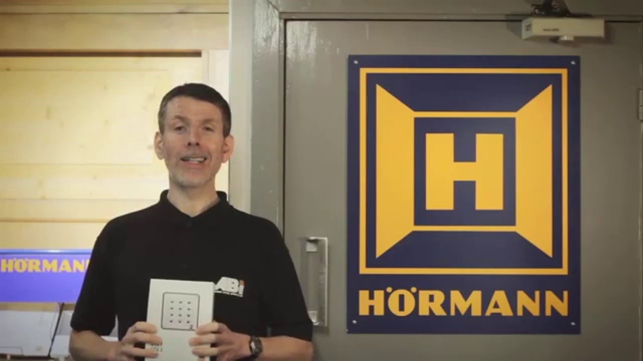
How to set up the Hörmann CTV 1 and CTV3 Digital Keypads
The Hörmann CTV keypads are digital external keypads that allow a user to open and close their garage door (or any device that accepts a volt free relay impulse) using a 3 – 5 digit pin number.
The CTV1 has a single relay output and can control a single device and the CTV3 has 3 relay outputs, although only 2 can be used as direct control relays with the third relay providing additional options for the Hörmann automation systems. In this article we will focus on the direct control aspect of the devices and demonstrate setting up the units to open and close your garage door. Both the CTV1 and CTV3 are supplied with an external keypad and an internal control unit. The external keypad comes complete with a fixed cable of 5m. This can be shortened or extended up to 20m.
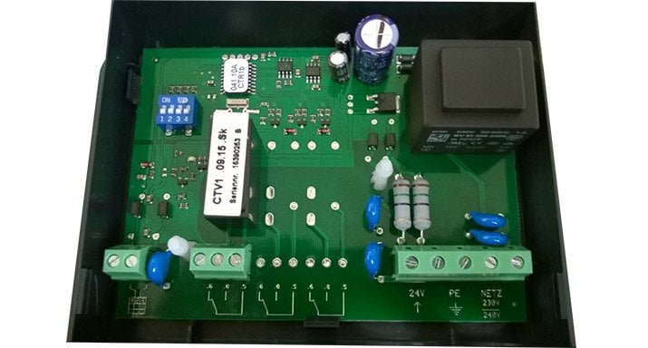
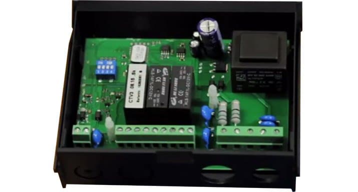
The internal control unit provides connections for a power source, the relay outputs and the connection to the keypad.
Keypad
CTV1
CTV3
Setting the code
The dip switch can then be set back to the off position.
To activate the corresponding relay and operate the door the user can then enter the pin number followed by the ‘key’ symbol on the keypad.
Wiring Diagrams
The illustration below details a typical wiring scenario with the CTV1 connected to a Hörmann BiSecur SupraMatic series 3 automatic operator.
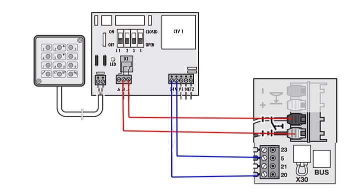
The illustration below details the connections for a CTV3 with a 240v mains connection and two relay outputs connected to two automation systems.
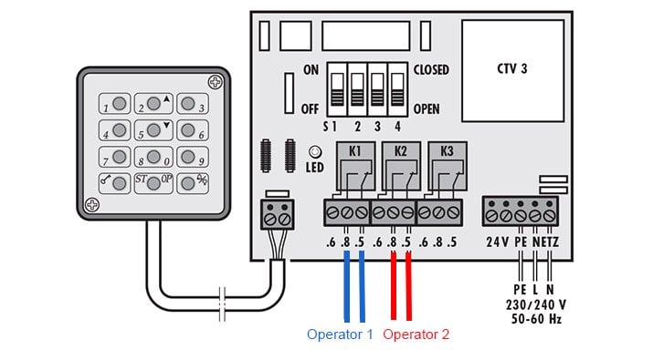
Wiring Diagrams
Check out more guides on our decdicated technical page.
We also cover the whole of the Yorkshire region including, Wakefield, Leeds, Huddersfield and surrounding areas.
